1. Test bed system architecture
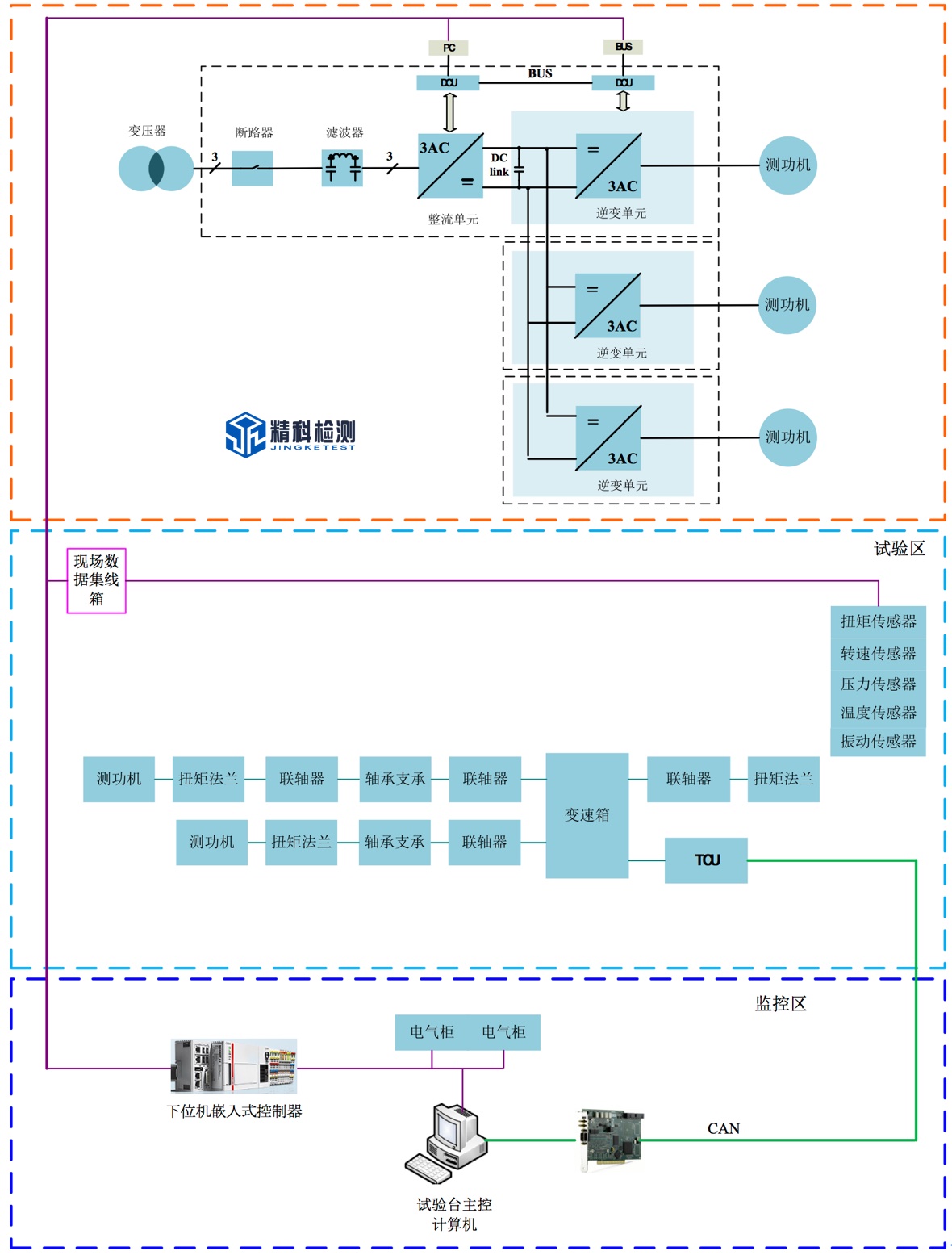
The test bench consists of a power zone, a test zone and a monitoring zone. The power zone is mainly composed of motor control inverters, electrical control cabinets, etc.; the test zone is mainly composed of electric dynamometers, measuring sensors, electric dynamometer cooling systems, tested gearboxes, benches, tooling and shock-absorbing installation platforms, etc. ; The monitoring area is mainly composed of a main control computer and an electric control cabinet.
The inverter in the power zone is responsible for controlling the drive motor and load motor of the dynamometer. The drive motor simulates the power source (motor or engine) of the tested gearbox, and the load motor simulates the road load. When the drive motor is used for speed control, it is generally in an electric state, and the load motor is in a power generation state. The electric energy generated by the load motor is fed back to the drive motor through the DC bus of the frequency converter, forming an internal electrical enclosed structure. When encountering an emergency, the kinetic energy of the motor can be consumed through the braking resistor. The drive motor and the load motor can have a variety of control methods, and the various control methods can be flexibly switched, which can be used for drive control or load control.
The test area is used for the test of the test piece. The dynamometer in the test area can control the speed and torque to simulate the road load. The load simulation methods include: constant torque control, road spectrum input, calculated road spectrum, and user-defined Load spectrum and other methods.
The monitoring area is composed of main control computer, data acquisition system, sensor signal processing system, real-time controller, operation console, etc. The main control computer and the dynamometer driver communicate through communication methods such as Ethernet to realize load simulation. The data acquisition system is responsible for the data acquisition of various sensors on site, the data acquisition system transmits the data to the upper computer in real time, and the main control computer reads the data from the real-time controller in real time. The monitoring system saves, displays, and performs various calculations on the data. The system monitors the vibration status of the motor under test, the bearing seat of the test bench, and the dynamometer in real time through the vibration sensor. Once the system is abnormal, the main control computer takes corresponding measures to stop the dynamometer and the motor under test to prevent deep fault damage and record at the same time All the data before the shutdown, the user can call for analysis. The main control computer reserves 4 CAN bus interfaces to communicate with the TCU of the tested gearbox. The system develops a CAN communication protocol for the user, and the user can edit it by himself.
In addition, the system is also equipped with an early fault diagnosis system to perform early failure fault diagnosis and analysis on the test piece, and early failure warning and analysis on the rotating parts such as gears and bearings of the test piece.
The three dynamometers can be independently controlled, which can meet the test of the reducer, and can also disconnect the drive end dynamometer to realize the powertrain test (adding the battery simulator); it can also be expanded to a four-power dynamometer with a hybrid reducer Test Bench.
2. Key technical indicators
1) Torque measurement accuracy: ±0.05%FS~±0.1%FS
2) Pulse resolution of speed sensor: 1024/600pprppr
3) Torque control accuracy: ±0.5%~±1%
4) Speed control accuracy: ±0.01%FS
5) The maximum vibration speed value of the dynamometer (RSM): ≤2mm/s (independent), ≤3.5mm/s (loading)
6) Temperature rise of intermediate bearing seat: ≤35℃
7) The maximum vibration speed value of the intermediate bearing seat (RSM): ≤2mm/s (independent), ≤3.5mm/s (loading)
8) Test motor current measurement channels: 4/6 channels
9) Test motor voltage measurement channels: 4/6 channels
10) Power analyzer measurement accuracy: ± (0.05%/01% of reading + 0.05%/0.1% of range)
11) Sampling rate of data acquisition system: 1kHz
12) User data acquisition system channel: optional
13) Temperature measurement range: -50℃~200℃
14) Vibration sensor measuring range (RSM): 0~20mm/s
3. Main test items of the test bench
1) Overspeed test
2) Transmission efficiency test
3) Differential speed test performance test
4) Differential reliability test
5) Speed-torque characteristic test
6) Powertrain efficiency test (efficiency MAP, supporting DC bidirectional power supply and power analyzer, for EV powertrain/hybrid)
7) Speed control accuracy test (for EV powertrain/hybrid)
8) Torque control accuracy test (for EV powertrain/hybrid)
9) Speed response time test (for EV powertrain/hybrid)
10) Torque response time test (for EV powertrain/hybrid)
11) Accelerated performance test
12) Electric working condition test (supporting DC bidirectional power supply and power analyzer, for powertrain/hybrid)
13) Power generation condition test (supporting DC bidirectional power supply and power analyzer, for powertrain/hybrid)
14) Vibration detection
15) Noise detection
16) Road spectrum simulation test
17) Fatigue test
18) Complete the dynamic tightness test
19) The test bench detects objects: reducers for pure electric passenger cars with rated input power not greater than 250kw, passenger car AT, DCT, AMT, CVT automatic transmission.
4. Description of key technology of motor test bench
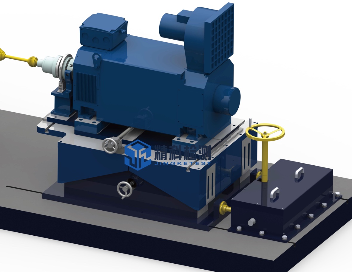
4.1 High performance electric dynamometer
The drive motor adopts a high-speed, low-inertia motor with a small center height, with a minimum center height of 132mm, which can meet almost all the requirements of the transmission input shaft and output shaft spacing.
The loading dynamometer adopts a low-inertia synchronous motor or asynchronous motor. If high dynamic testing is required, it is recommended to select a very low-inertia synchronous motor as the loading dynamometer.
The front and rear bearing sides of the dynamometer are designed with vibration monitoring, and the three-phase windings and bearings of the motor are designed with temperature monitoring.
4.2 High dynamic real-time control system
The monitoring system of the motor test bench is controlled by an embedded real-time controller, and EtherCAT communication can achieve high dynamic control. The system's no-load dynamic response time can reach within 10ms, which can meet the test of complex variable conditions.
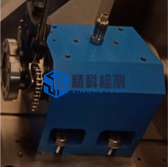
4.3 Precision mechanical structure
The mechanical structure parts are processed by high-precision machining center, with very high machining accuracy, and the shaft coaxiality is better than 0.02mm.
4.4 Precision high-speed bearing support
High-speed bearing support adopts high-speed angular contact ball bearings, spring preloaded, bearing temperature rise does not exceed 35℃, vibration speed at the highest speed is less than 2.5mm/s (RSM), grease lubrication, maintenance-free, and can run continuously for 20,000 hours.
4.5 Adjustable spatial position
Adjustment direction: height; adjustment range: ±50mm; adjustment method: manual adjustment; locking method: bolt locking.
Adjustment direction: height; adjustment range: ±100mm; horizontal axis ±200mm; horizontal radial; adjustment range: ±80mm; adjustment method: manual adjustment; locking method: bolt locking.
4.6 Perfect safety protection measures
1. Real-time monitoring of the front and rear bearings and temperature of the dynamometer, real-time monitoring of the current and voltage of the dynamometer, and real-time monitoring of the speed and torque of the dynamometer.
2. The bearing temperature and vibration of the middle high-speed bearing support are monitored in real time.
3. Real-time monitoring of the vibration of the motor under test.
4. The safety protection cover is closed for detection, forming a chain protection with the dynamometer.
5. The electronic control system has protection functions such as short circuit, leakage, power failure, overcurrent, and overvoltage.
6. The system software has a safety detection function. When the monitoring value exceeds the threshold, it will immediately alarm. The system has three levels of protection.
7. For the durability test, the system automatically predicts the trend based on the monitored historical data such as vibration. When the prediction fails, the system will prompt the user to pay attention.
4.7 Complete monitoring software
The motor test bench software adopts a modular design architecture. Users can customize the test process and working condition parameters to realize the control of the motor speed and torque. The system classifies users and opens different functional modules. The system has the function of automatic zero point calibration at startup. The software has a dedicated sensor calibration module, and users can calibrate the sensor regularly. The communication interface with EUT is reserved to realize the control of EUT. It has the following functions:
1. Speed control
2. Torque control
3. Temperature monitoring
4. Speed monitoring
5. Security features
6. Have a standard communication interface with the host computer software
7. The limit monitoring of the tested part and the test bench can be carried out to ensure that the speed of the tested part and abnormalities can be in a very short time
8. Restore to a safe state within
9. Open loop and closed loop control of speed and torque
10. Road simulation
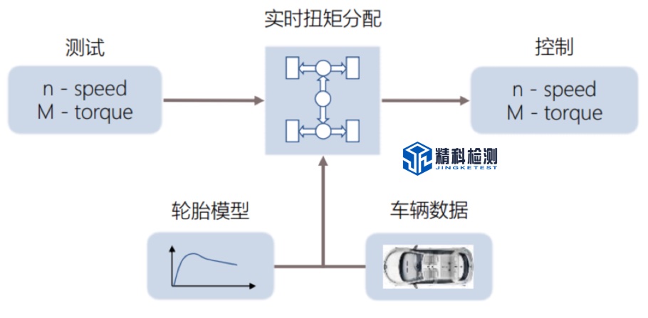
The vehicle road simulation function is integrated in the real-time controller. The vehicle road simulation function is used to realize the road resistance, slope resistance simulation and inertia simulation of the vehicle on the bench. These resistance simulations can be expressed by the following formula:
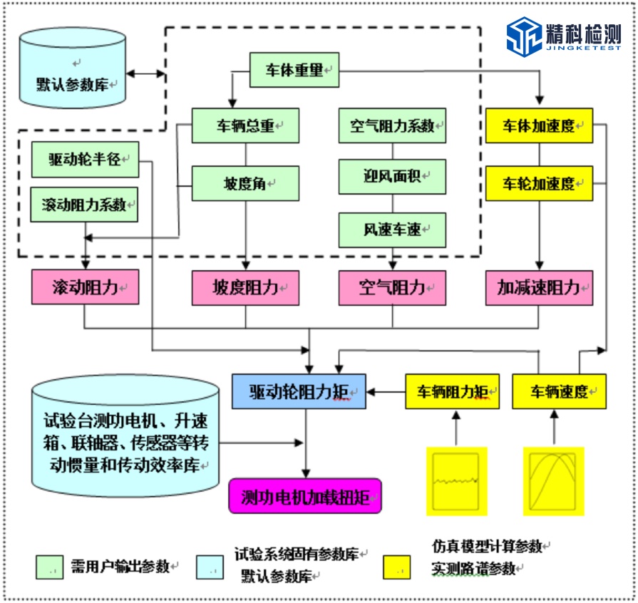
The system can provide various series of dynamometer electromechanical inertia simulation, and simulate the road load according to the equation:
RL = F0 + F1VX+ F2Vn+ I dv/dt + mg * (Grad/100)
among them:
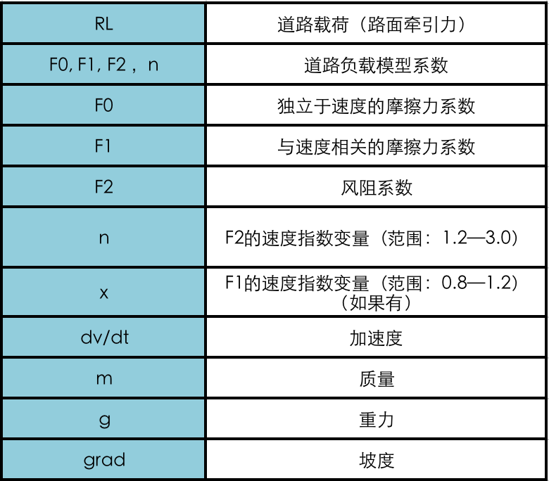
The parameters F0, F1, F2, n, and x (if any) form the road load model, and they can be obtained in a variety of ways.
11. System interface
Communication control interface with environmental warehouse;
Communication control interface with cooling system;
Communication control interface with battery simulator;
Communication control interface with frequency converter;
Communication control interface with INCA calibration system;
Four CAN buses, which can communicate with the test piece;
One Ethernet communication interface;
Provide the corresponding cable.


