Service hotline: 0551-62885653 / 18164485259

Home / Solution / High-speed motor (dynamometer) test system

loading

High-speed motor (dynamometer) test system

The real-time dynamic control system of the high-speed motor test bench can realize the speed and torque control through the real-time controller and simulate the actual load. The main control system can communicate with the environmental chamber, power analyzer, cooling system, EUT, etc., and realize control. The data acquisition system collects signals from torque sensors, vibration sensors, temperature sensors, pressure sensors, and other sensors, and transmits them to the main control system at a high speed. The sensor data can be displayed, saved and processed in the software interface.
Availability:
Quantity:
sharethis sharing button

The real-time dynamic control system of the high-speed motor test bench can realize the speed and torque control through the real-time controller and simulate the actual load. The main control system can communicate with the environmental chamber, power analyzer, cooling system, EUT, etc., and realize control. The data acquisition system collects signals from torque sensors, vibration sensors, temperature sensors, pressure sensors, and other sensors, and transmits them to the main control system at a high speed. The sensor data can be displayed, saved and processed in the software interface.


1. High-speed and high-power motor test system

The high-speed and high-power motor test bench (test system) can be used in various high-speed motor applications such as new energy vehicle drive motors, high-speed air compressor motors, and high-speed magnetic levitation motors. The installation platform can be designed according to the motor to be tested, and the end flange installation structure or the base installation structure can be selected.

Motor test bench selection specifications

Select the dynamometer according to the characteristic curve of the motor to be tested. The dynamometer is generally controlled by a four-quadrant inverter and can work in electric or power generation. The system can be equipped with high and low temperature environment chambers, battery simulators or DC bidirectional power supplies, and power analysis Instrument, cooling system and other accessories.

The recommended dynamometer parameters are as follows:

9990909

Note: E—with environmental compartment (optional)

P—With battery simulator or DC two-way power supply (optional)


2. Small high-speed motor test system

The small high-speed motor test bench (test system) is used to test low-power high-speed motors. It is mainly used for low-power aviation generators, robot motors, small high-speed compressor motors, machine tool spindle motors, etc. Motor test. The installation platform can be designed according to the motor to be tested, and the end flange installation structure or the base installation structure can be selected.

Motor test bench selection specifications

Select the dynamometer according to the characteristic curve of the motor to be tested. The dynamometer is generally controlled by a four-quadrant inverter and can work in electric or power generation. The system can be equipped with high and low temperature environment chamber, battery simulator or DC bidirectional power supply, low power Adjustable DC power supply, power analyzer, cooling system and other accessories. According to users' requirements for noise, water-cooled dynamometer or air-cooled dynamometer can be selected,

The recommended dynamometer parameters are as follows:

Parameter table of air-cooled dynamometer:

2-4


Parameter table of water-cooled dynamometer:

2-5


3. Ultra-high speed motor test system

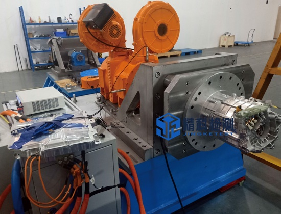
The ultra-high-speed motor test bench (test system) is used to test high-speed motors with a speed above 60,000 rpm, and is generally used in fields such as high-speed compressor motors. Our company can provide a high-speed motor test bench with a speed of 165000rpm.


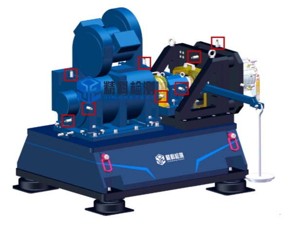
The ultra-high-speed motor test system is composed of dynamometer, dynamometer driver, braking resistor, speed increasing box, DC power supply, power analyzer or power meter, control system, mechanical system, sensor measurement system and other parts.


1. Test bench bottom plate

2. Dynamometer part

3. Coupling between dynamometer and gearbox

4. High-speed gearbox

5. High-speed coupling, including the test piece support of the protective cover

6. Test piece

The main structure of the test bench

The mechanical structure of the test bench includes: test bench base, dynamometer installation base, bearing support, test piece installation tooling, locked-rotor mechanism, test piece connecting shaft, etc.


Test bench base

The base of the test bench adopts integral casting structure. The upper surface of the base is the assembly surface. After precision processing, four air spring shock absorbers are installed at the bottom of the base for shock isolation and shock absorption.


Ultra high speed gearbox

The ultra-high-speed gearbox adopts a two-stage power distribution gearbox with coaxial input and output shafts. The parameters are as follows:

1. Rated output speed: 165,000 rpm

2. Rated output torque: Tout, rated = 1.5 Nm

3. Rated power Pnom = 25 kW

4. The service life of all gearbox components> 10,000 hours


As a key component of the ultra-high-speed gearbox system, the lubrication pumping station is extremely important. The pumping station is provided by the ultra-high-speed gearbox supplier at the same time, and joint adjustment is carried out before leaving the factory.

Test piece torque measurement

The torque measurement of the test piece adopts a direct measurement method, instead of installing the torque speed sensor on the low-speed end to measure, avoiding the transmission loss of the high-speed gearbox into the measurement data of the test piece motor.


Test piece connection

In order to facilitate the user to test different specimens, to facilitate the replacement of the connection tooling, and to avoid the torsional vibration of the shaft system, a torque flange, a transitional spline flange, and a spline are installed between the output end of the bearing housing and the input shaft of the motor under test. axis.


1. System architecture of motor test bench

The real-time dynamic control system of the motor test bench can realize the speed and torque control through the real-time controller and simulate the actual load. The main control system can communicate with the environmental chamber, power analyzer, cooling system, EUT, etc., and realize control. The data acquisition system collects signals from torque sensors, vibration sensors, temperature sensors, pressure sensors, and other sensors, and transmits them to the main control system at a high speed. The sensor data can be displayed, saved and processed in the software interface.


2. Key technical indicators

1) Torque measurement accuracy: ±0.05%FS~±0.1%FS

2) Pulse resolution of speed sensor: 1024/600pprppr

3) Torque control accuracy: ±0.5%~±1%

4) Speed ​​control accuracy: ±0.01%FS

5) The maximum vibration speed value of the dynamometer (RSM): ≤2mm/s (independent), ≤3.5mm/s (loading)

6) Temperature rise of intermediate bearing seat: ≤35℃

7) The maximum vibration speed value of the intermediate bearing seat (RSM): ≤2mm/s (independent), ≤3.5mm/s (loading)

8) Test motor current measurement channels: 4/6 channels

9) Test motor voltage measurement channels: 4/6 channels

10) Power analyzer measurement accuracy: ± (0.05%/01% of reading + 0.05%/0.1% of range)

11) Sampling rate of data acquisition system: 1kHz

12) User data acquisition system channel: optional

13) Temperature measurement range: -50℃~200℃

14) Vibration sensor measuring range (RSM): 0~20mm/s


3. Main test items of motor test bench

1. Motor with controller power and torque characteristic test

2. Temperature rise test of motor with controller

3. Motor with controller locked-rotor test

4. Motor controller control strategy development verification test

5. Motor drives the maximum speed test of the controller

6. Motor with controller braking regenerative energy feedback test

7. Motor external characteristic test

8. Development and matching optimization test of motor and controller powertrain

9. Performance test and calibration test of motor and controller powertrain

10. Efficiency Map test

11. Accelerated response test

12. Torque response test

13. Durability test of steady-state cyclic loading

14. Back EMF constant and waveform

15. Electromechanical time constant

16. Motor response characteristic test (Note: The time resolution is required to reach the subtle level here, which is generally used for high-speed small motor testing)

4. Description of key technology of motor test bench

4.1 High performance electric dynamometer

One of the core components of the motor test bench is the dynamometer. The high-speed dynamometer used has the characteristics of low moment of inertia, low vibration speed, small size, good acceleration performance and efficiency. Real-time monitoring of the front and rear bearings, three-phase windings and bearing temperature of the dynamometer.

4.2 High dynamic real-time control system

The monitoring system of the motor test bench is based on an embedded real-time controller and adopts EtherCAT/Profinet communication to achieve high dynamic control. The system's no-load dynamic response time can reach within 10ms, which can meet the test of complex variable conditions.

4.3 Convenient electrical parameter measurement system

The electrical parameter measurement system uses high-precision power analyzers and current transformers, which can simultaneously access torque and speed signals to measure the efficiency, current, voltage and other parameters of the motor and controller.


4.5 Precision mechanical structure

The mechanical structure parts are processed by high-precision machining center, with very high machining accuracy, and the shaft coaxiality is better than 0.02mm.


4.6 Precision high-speed bearing support

  • High-speed angular contact ceramic ball bearings

  • Spring preload

  • Bearing temperature rise does not exceed 35℃,

  • Vibration speed is lower than 2.5mm/s (RSM) at maximum speed

  • Grease lubrication, maintenance-free, can run continuously for 20000 hours


4.7 Perfect safety protection measures

1. Real-time monitoring of the front and rear bearings and temperature of the dynamometer, real-time monitoring of current and voltage, real-time monitoring of speed and torque, and real-time vibration monitoring of the front and rear ends.

2. The bearing temperature and vibration of the middle high-speed bearing support are monitored in real time.

3. Real-time monitoring of the vibration of the motor under test.

4. The safety protection cover is closed for detection, forming a chain protection with the dynamometer.

5. The electronic control system has protection functions such as short circuit, leakage, power failure, overcurrent, and overvoltage.

6. The system software has a safety detection function. When the monitoring value exceeds the threshold, it will immediately alarm. The system has three levels of protection.

7. For the durability test, the system automatically predicts the trend based on the monitored historical data such as vibration. When the prediction fails, the system will prompt the user to pay attention.


4.7 Easy installation

The L mounting bracket of the motor test bench is designed with a positioning stop and a positioning mounting surface; through the transitional mounting flange connection with the test motor, the test motor can be quickly installed without centering adjustment. The L-shaped mounting bracket is designed with an interface to the high and low temperature environment chamber, and the test motor can be placed in the high and low temperature environment chamber for testing. Vibration sensors are installed in the X/Y/Z directions of the L-shaped installation tooling to monitor the vibration status of the motor under test in real time. The interface with the environmental chamber adopts four-pillar cantilever support, which can ensure that the axis of the test motor can be coaxial with the shaft system of the test bench when the high and low temperature environment changes.


For small high-speed motors, the dynamometer can be adjusted in the axial position, and the mounting platform of the motor under test can be adjusted in the vertical direction to adapt to the motors to be tested of different sizes.


4.8 Complete monitoring software

The motor test bench software adopts a modular design architecture. Users can customize the test process and working condition parameters to realize the control of the motor's speed and torque. The system classifies users and opens different functional modules. The system has the function of automatic zero point calibration at startup. The software has a dedicated sensor calibration module, and users can calibrate the sensor regularly. The communication interface with EUT is reserved to realize the control of EUT. It has the following functions:

1. Speed ​​control

2. Torque control

3. Temperature monitoring

4. Speed ​​monitoring

5. Safety function

6. Have a standard communication interface with the host computer software

7. The limit monitoring of the DUT and the test bench can be performed to ensure that the rotation speed of the DUT and abnormalities can be extremely short

To a safe state within a period of time.

8. Open loop and closed loop control of speed and torque


Control interface 1


Control interface 2


9. Road simulation

The vehicle road simulation control model is integrated in the real-time controller. The vehicle road simulation function is used to realize the road resistance, slope resistance simulation and inertia simulation of the vehicle on the bench. These resistance simulations can be expressed by the following formula:

The system can provide various series of dynamometer electromechanical inertia simulation, and simulate the road load according to the equation:

RL = F0 + F1VX+ F2Vn+ I dv/dt + mg * (Grad/100)

among them:

2-6

The parameters F0, F1, F2, n, and x (if any) form the road load model, and they can be obtained in a variety of ways.

10. System Interface

  • Communication control interface with environmental warehouse;

  • Communication control interface with cooling system;

  • Communication control interface with battery simulator;

  • Communication control interface with frequency converter;

  • Communication control interface with INCA calibration system;

  • Four CAN buses, which can communicate with the test piece;

  • One Ethernet communication interface;

  • Provide the corresponding cable.

4.9 Shaft alignment measures

For high-speed shafting, we need to ensure that the coaxiality of the shafting is not greater than 0.02mm. Generally, the following measures are taken:

  • Laser alignment tool alignment

  • With fine-tuning mechanical structure


4.10 Treatment measures for shafting dynamic balance

The dynamic balance accuracy of the shaft system of the high-speed motor test bench reaches G1, and it is dynamically balanced on site. The general measures are as follows:

  • The flange on the shaft system is designed with uniform threaded holes for counterweight

  • Use on-site dynamic balancer for dynamic balance


Previous: 
Next: 

© 2020 Anhui JINGKETEST Technology Co., Ltd. All rights reserved /Anhui ICP No. 17025439-1

Consultation hotline: 0551-62885653 / Monday to Sunday: 9:00-17:00