1. System Architecture
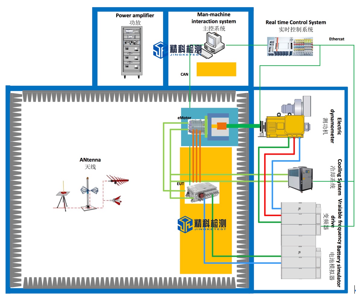
The electric drive EMC/EMI test system is generally composed of electric wave anechoic chamber, dynamometer system and measuring instrument. We generally provide anechoic chamber and dynamometer system. The anechoic chamber can be a standard CISPR25 anechoic chamber. The dynamometer system needs to be determined according to the parameters of the product to be tested. The dynamometer system generally includes: a power dynamometer that simulates a load, a through-wall shielding shaft system, an installation stand, a frequency converter, a battery simulator, a cooling system, a sensor measurement system, a data acquisition system, and monitoring software.
2. Key technical indicators
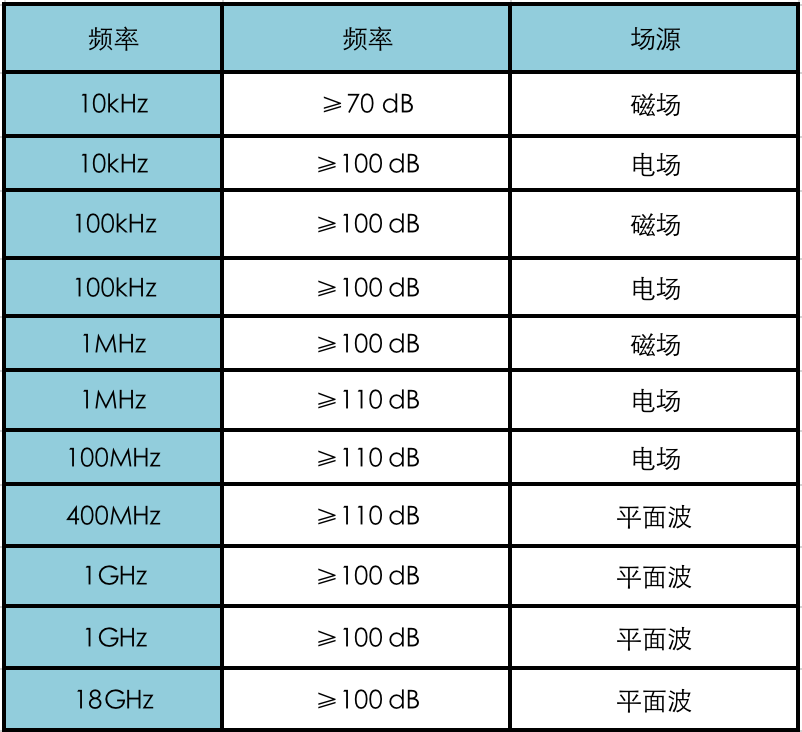
2.1 Shielding effectiveness-(SE)
The shielding effectiveness of the electric drive EMC loading CISPR25 darkroom, control room, and power amplifier room is implemented in accordance with the standard EN50147-1 or the latest GB/T12190 standard (frequency range 10KHz~18GHz). The specific test frequency is determined according to the test frequency of the third-party testing agency, and meets the following indicators:
After the installation of all relevant accessories (including the wall shaft) is completed, the electric drive EMC dynamometer works (small non-radiation load can be provided), and the monitoring system, lamps, antenna tower work, and the filter are energized, the shielding effectiveness The level is at least 10dB lower than the Class 5 limit (PK&QP&AV) specified by CISPR25.
2.2 Measurement control accuracy
1) Torque measurement accuracy: ±0.05%FS
2) Pulse resolution of speed sensor: 1024/600pprppr
3) Torque control accuracy: ±1%
4) Speed control accuracy: ±0.01%FS
5) The maximum vibration speed value of the dynamometer (RSM): ≤2mm/s (independent), ≤3.5mm/s (loading)
6) Temperature rise of intermediate bearing seat: ≤35℃
7) The maximum vibration speed value of the intermediate bearing seat (RSM): ≤2mm/s (independent), ≤3.5mm/s (loading)
8) Sampling rate of data acquisition system: 1kHz
9) User data acquisition system channel: optional
10) Temperature measurement range: -50℃~200℃
11) Vibration sensor measuring range (RSM): 0~20mm/s
2.3 Long-line method-(LWM)
According to the latest version of CISPR25, the Modelled long wire antenna method (LWM) is adopted in the frequency range of 150kHz~1GHz, and the error of more than 90% of the actual test points is not more than ±6dB compared with the theoretical value of the model. The test area is the motor side and the non-motor side. The test invites an authoritative third-party measurement agency to conduct the test and provide a report.
2.4 Background noise-(ABN)
When there is no DUT, monitoring system, lamps, and filters are energized, in the range of 9KHz~6GHz, the test background noise level should be at least lower than the level of the Class 5 limit (PK&QP&AV) specified in the latest version of CISPR25 10dB, which is at least 6dB lower than the GJB151B RE102 limit. This test invites third-party measurement institutions certified by the state to conduct tests and provide reports.
2.5 Air quality
After the construction of the radio anechoic chamber is completed, an inspection agency with CNAS and CMA qualification \"HuaTest\" shall be invited to conduct air quality testing in the darkroom and issue a test for the air quality in the darkroom (including at least formaldehyde, benzene, toluene, dimethylbenzene and TVOC) Report, the test results meet the limit requirements of GB50325-2010 \"Indoor Environmental Pollution Control Regulations\" and GB/T 18883-2002 \"Indoor Air Quality Standards\".
2.6 Grounding resistance
The anechoic chamber and shielding room are grounded by single-point grounding, and the grounding resistance is designed and constructed by us. The grounding device process uses physical resistance reducers, but does not use chemical resistance reducers. The grounding device is designed to be maintainable. The grounding resistance of dark room and shielded room is less than 1Ω.
3. Implementation standards
1. CISPR16-1-4 \"Specifications for Radio Interference and Immunity Test Equipment and Methods Part 1-4: Radio Interference and Immunity Test Equipment Radiated Interference by Auxiliary Equipment\"
2. CNAS-CL01-A008 \"Instructions for the Application of Testing and Calibration Laboratory Competence Criteria in the Field of Electromagnetic Compatibility Testing\"
3. EN50147 \"Measurement method of shielding effectiveness of high-performance shielded room\"
4. GB/T 12190 \"Measurement Method of Shielding Effectiveness of Electromagnetic Shielding Room\"
5. ISO 4589-2 \"Plastics-Determination of burning behaviour by oxygen index Part 2: Ambient-temperature test\"
6. GB/T2406 Plastic Combustion Performance Test Method Oxygen Index Method
7. GB 8624 Classification of burning performance of building materials and products;
8. ISO 11452-1/-2/Road vehicles-Test methods for immunity of electronic/electrical components to narrowband radiated electromagnetic energy-Radio anechoic chamber method;
9. CISPR 25 \"Limits and Measurement Methods of Radio Disturbance Characteristics of Vehicles, Ships and Internal Combustion Engines Used to Protect Vehicle-mounted Receivers\"
10. MIL-STD-461G REQUIREMENTS FOR THE CONTROL OF ELECTROMAGNETIC INTERFERENCE CHARACTERISTICS OF SUBSYSTEMS AND EQUIPMEN
11. GJB 151B \"Requirements and Measurements for Electromagnetic Emission and Sensitivity of Military Equipment and Subsystems\"
12. GBT 36282-2018 \"Electric Vehicle Drive Motor System Electromagnetic Compatibility Requirements and Test Methods\"
13. GB 50325-2010 \"Code for Indoor Environmental Pollution Control of Civil Construction Engineering\"
14. GB/T18883-2002 \"Indoor Air Quality\"
4. Key technology description
The key technologies of the EMC test system for motors and drives include: high-speed wall-through shielding shafting, complete electrical isolation system, dark room non-radiation sensor monitoring system, low-noise battery simulator and other systems, real-time monitoring system and other parts.
4.1 High-speed through-wall shielding shafting
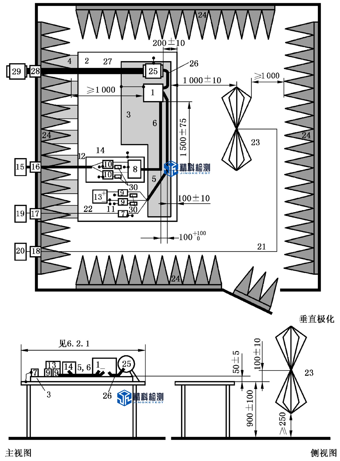
CISPR25 defined test layout
The CISPR25 standard clearly requires that the distance between the controller EUT and the center of the absorbing material is not less than 1m. For the three-in-one electric drive assembly, the distance between the inner side of the controller (near the darkroom side) and the top of the absorbing material is not less than 1m, and the distance between the mounting end of the motor drive assembly and the top of the absorbing material is not less than 1m. In order to meet this requirement, the length of the shaft system is longer, and at the same time, it needs to meet the requirement of less vibration at high speed. The current foreign solution is to use carbon fiber shaft or glass fiber shaft, the test conditions require that the length of the shaft must be greater than 1.6 meters (international standards stipulate that the distance between the end face of the motor under test and the top of the anechoic chamber absorbing material is not less than 1m, considering the absorbing material Thickness, ferrite thickness, and shield thickness, while also taking into account the error during installation). Although these two non-metallic shafts are excellent materials that are non-conductive and non-magnetic, because the electric drive system of new energy vehicles has entered the stage of high-speed and high-torque, the absolute elastic modulus of glass fiber or carbon fiber shafts is not suitable for high-speed and high-torque testing. Scenes.
The high-speed through-wall shielding shaft designed by our company has the following characteristics:
1. Adopt high-precision and low-inertia rigid shaft, while taking into account the characteristics of high speed and large torque.
2. As a part of the anechoic chamber, the rotating shaft has good conductivity, fundamentally shields external electromagnetic radiation, achieves an excellent shielding effect, and reduces background noise in the darkroom.
3. Through the detachable shielding cover, the test motor can be completely shielded, and the electromagnetic compatibility characteristics of the drive axle can be tested independently.
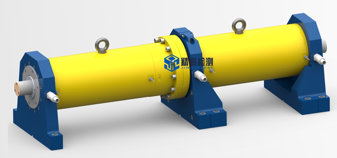
In order to meet the high-speed, large-torque and shielding requirements at the same time, the system adopts a high-precision long-axis system.
1. The vibration speed in the full speed range is less than 3.5mm/s.
2. The shaft system adopts a multi-point support structure, which is convenient for centering the base in the dark room and the coaxiality is better than 0.02mm.
3. The shaft system has a fully dynamic balance structure, and the dynamic balance accuracy reaches G1.
4. The first-order critical speed of the shaft system is higher than the maximum speed of the system.
4.2 Completely electrically isolated system
In order to prevent electromagnetic waves and charges from being conducted outside the anechoic chamber to the anechoic chamber, in addition to special electromagnetic shielding methods, the dynamometer must be completely electrically isolated. Electric drive motors or powertrains need to meet single-point grounding requirements.
1. The dynamometer and the shielded shaft adopt high-speed insulation coupling.
2. The dynamometer is completely electrically isolated from the base.
3. The high-speed shielded shaft and the tested electric drive motor shaft adopt high-speed insulation coupling.
4. The installation base in the anechoic chamber is completely electrically isolated from the anechoic chamber.
5. The anechoic chamber is designed with a removable complete shielding cover, which can completely shield the motor and test the EUT of the controller individually.
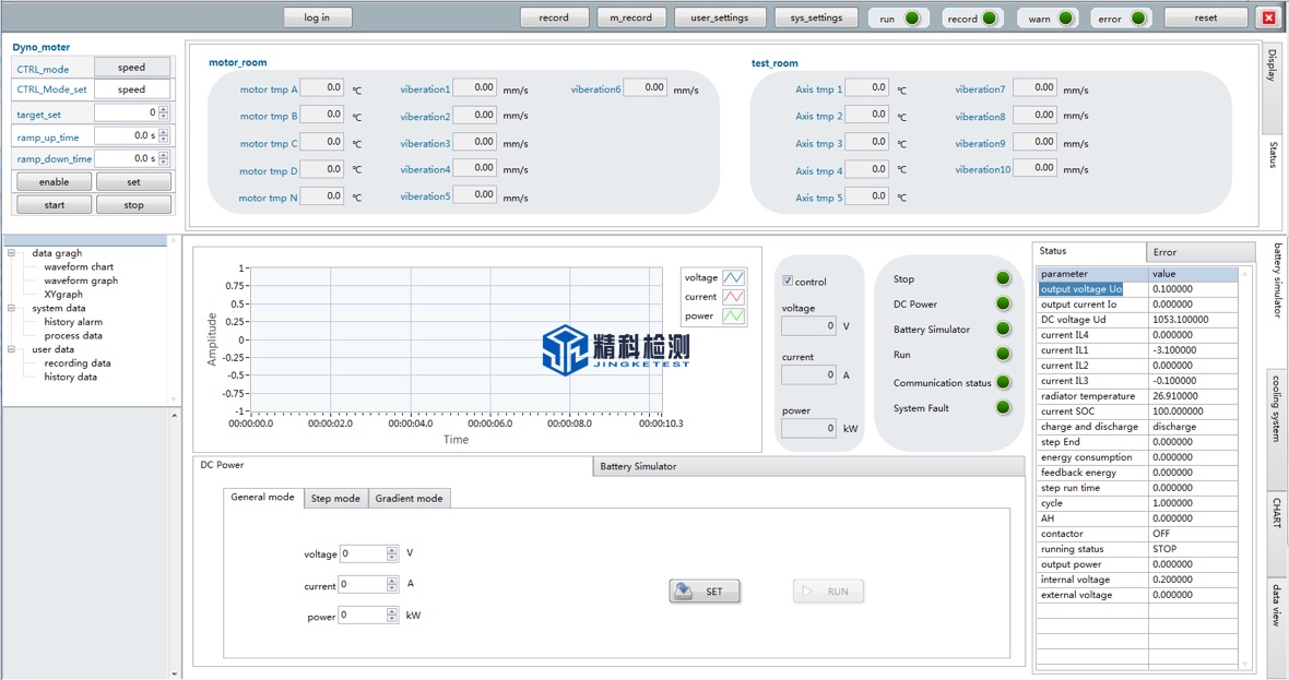
4.3 Non-radiation sensor monitoring system in dark room
The electric drive system and shaft system under test in the anechoic chamber are all designed with vibration and temperature monitoring sensors. The sensors need to be collected by a high-speed data acquisition system and transmitted to the monitoring software for signal analysis and processing. The data acquisition system is placed in the anechoic chamber. Due to its own radiation, the background noise of the anechoic chamber will be affected, and low noise processing is required.
Our company has made the following designs for the data acquisition system in the anechoic chamber:
1. The power supply of the data acquisition system is filtered by a 24V filter to eliminate the power interference entering the electric wave dark room.
2. The signal transmission design of the data acquisition system. Real-time Ethernet optical fiber converter, through optical fiber and optical fiber waveguide installed on the wall of the anechoic chamber, transmits the signal to the anechoic chamber, and then converts it into a digital signal through an inverse converter, and enters the upper position In the machine.
3. The data acquisition system is installed in a shielded box. The shielded box is designed with ventilation waveguides to ensure heat dissipation and at the same time ensure that the electromagnetic waves in the box will not be transmitted to the dark room.
4. The sensor cable adopts a special shielded cable, which connects the sensor and the shielded box as a whole.
4.4 Low noise battery simulator
The battery simulator supplies power to the motor controller under test, can simulate the battery, and can also perform battery pack charge and discharge tests.
1. Output voltage:
Maximum output voltage (Unom): 1200V
Output voltage range: 20V~Unom adjustable, setting resolution: 0.1V
Repeatability: ≤0.1% Unom
Voltage rise time (10% to 90% Unom): <5ms (resistive load)
Load change (10% to 90%) control time: ≤1ms (resistive load)
Residual ripple: ≤0.2% Unom effective value (frequency DC-1MHz)
2. Output current:
Maximum output current (Inom): 800A
Output current range: 0~Inom adjustable, setting resolution: 0.1A
Repeatability: ≤0.1% Inom
Current rise time (10% to 90% Inom): <1ms (resistive load)
Load change (10% to 90%) control time: ≤1ms (resistive load)
Temperature coefficient: ≤0.01% Inom/K
Residual ripple: ≤0.2% Inom effective value (frequency DC-1MHz)
3. Output power: ±350kW
4. Output efficiency: >90%
5. Output accuracy: 0.1%
6. Internal resistance:
The parameters of the battery simulator can be customized according to actual needs.
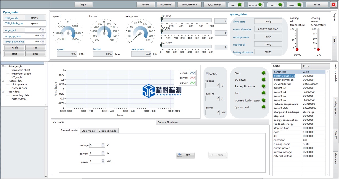
4.5 Real-time monitoring system
The monitoring system adopts embedded real-time controller control, real-time Ethernet communication, and all communication cables entering the control room are transmitted through optical fibers.
1. Real-time monitoring of the front and rear bearings and temperature of the dynamometer, real-time monitoring of the current and voltage of the dynamometer, and real-time monitoring of the speed and torque of the dynamometer.
2. Shield the real-time monitoring of the vibration of the long axis.
3. Real-time monitoring of the vibration of the motor under test.
4. The electronic control system has protection functions such as short circuit, leakage, power failure, overcurrent, and overvoltage.
5. The system software has a safety detection function. When the monitoring value exceeds the threshold, it will immediately alarm. The system has three levels of protection.
6. The dark room adopts a non-electromagnetic radiation photoelectric isolation data acquisition system, which collects vibration sensor and temperature sensor signals in real time, and transmits them to the control room through optical fiber for real-time monitoring.
7. Emergency stop buttons are designed near the test table in the dark room, in the control room, near the dynamometer, etc.
4.7 Special interface
The design frequency range of the water/oil waveguide is 9kHz~18GHz, which achieves the same shielding effectiveness as the darkroom.

2. The gas path waveguide takes into account the hydrogen pressure (5MPa), the entire gas path waveguide is formed in one piece instead of being welded, which avoids possible air leakage points and meets the explosion-proof requirements. The design frequency range of the gas wave guide is 9kHz~18GHz, which achieves the same shielding effectiveness as the darkroom.
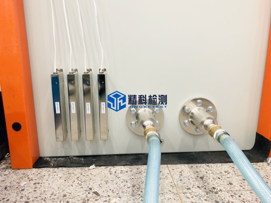
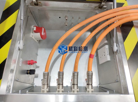
3. In order to ensure good shielding of the power supply line between the filter and the LISN, the darkroom provides high-voltage connectors, including under the raised floor of the darkroom, high-voltage shielded cables from the CP board high-voltage connector to the LISN end are used.